Section C.2 UML Diagrams

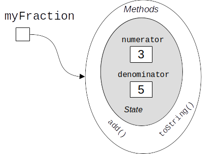
This figure was a great way to show how an object’s attributes are encapsulated, using methods to allow users to access them. However, it’s not exactly a compact or easy-to-draw representation. (Imagine the diagram for an object with five attributes and twelve methods!) There must be a better way, and it’s Unified Modeling Language diagrams, also called UML diagrams.
Aside

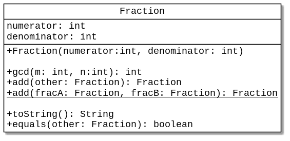
UML diagrams for objects are divided into three sections. The top section gives the name of the class. If the class is abstract, its name appears in italics. If there are any generics, they will also appear in the upper right corner of the top section.
The middle section lists the attributes. Unlike Java, where the data type precedes the attribute name, the attribute name comes first, followed by a colon and the data type.
The bottom section lists methods. Again, data types follow the parameter names, and the return type is last. The plus sign preceding each item means that the method is
public. If an attribute or method is private (as the attributes in this class should have been), they are preceded by a minus sign. Of special note is the second add method. It is a static method, and thus it is underlined in the UML diagram.
That’s pretty much it as far as creating a diagram for an object. Where things get interesting is when we want to make diagrams that show the relationships between objects, such as inheritance, composition, and aggregation.
Subsection C.2.1 Inheritance and Interfaces
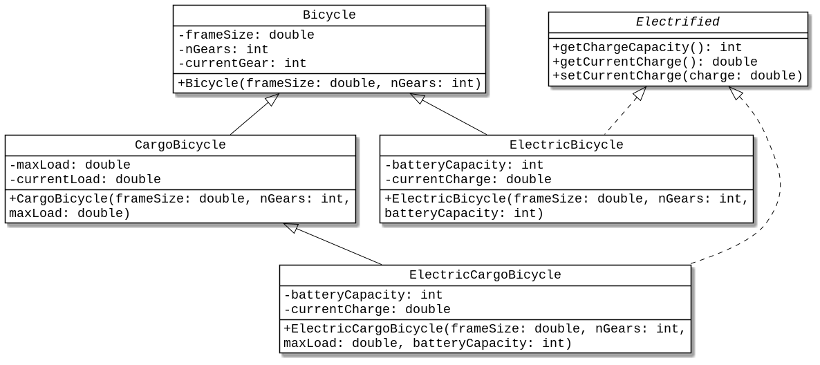
To show inheritance, draw an arrow with an open head from the child class to the parent class. To show that a class implements an interface, draw a dotted-line arrow with an open head from the implemented class to the implementing class.
Here is the diagram from Subsection A.4.2 showing that
ElectricBicycle and CargoBicycle inherit from Bicycle. ElectricCargoBicycle inherits from CargoBicycle. Both ElectricBicycle and ElectricCargoBicycle implment the Electrified interface.

Bicycle and its SubclassesNotice that the attributes for these classes are private; they are preceded by minus signs in the diagram.
Subsection C.2.2 Aggregation and Composition
The concepts of aggregation and composition are somewhat similar. The following description from Wikipedia (retrieved 30 Dec 2023) sums it up nicely:
Here is a UML diagram of the preceding paragraph. Aggregation is shown as an open diamond; composition as a closed diamond. The numbers show how many of each class can be aggregated (or composed). In this diagram, one university consists of from one to twenty departments. Each department (which can have zero or more instances) can have zero to five professors.

Don’t worry if you have trouble determining whether a particular situation calls for aggregation or composition; it is not always a clear-cut choice, and it can depend on the exact specification of the relationship between classes.
However, there is one very important point: as part of the design process, you draw your UML diagrams first, and generate the corresponding Java classes later. There are tools such as PlantUML that will help you draw UML diagrams from a text file description.
You have attempted of activities on this page.

