Runestone Academy can only continue if we get support from individuals like you. As a student you are well aware of the high cost of textbooks. Our mission is to provide great books to you for free, but we ask that you consider a $10 donation, more if you can or less if $10 is a burden.
Making great stuff takes time and $$. If you appreciate the book you are reading now and want to keep quality materials free for other students please consider a donation to Runestone Academy. We ask that you consider a $10 donation, but if you can give more thats great, if $10 is too much for your budget we would be happy with whatever you can afford as a show of support.
Every circuit in a computer is made by wiring together switches (transistors) so they implement logic gates. These logic gates are used to store information, do math, make comparisons, as well as everything else a computer can do.
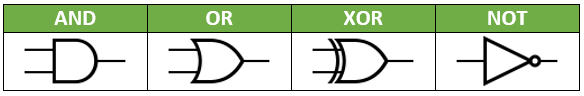
The diagrams for these circuits are drawn using the symbols shown below. Traditionally, the inputs to a gate come from the left, and the output comes out of the right side. That is why two lines are going into every gate but NOT… every other gate requires two inputs.
Key features:
AND has a flat left side and is rounder, OR bends in on the left and is pointier
XOR looks just like OR but with an extra line behind it
NOT has a little circle at the tip of a triangle
Below is an OR gate being used in a circuit. The power is wired to two push-button switches that function as the inputs to the circuit. The inputs can be turned off, in which case they do not transmit power, or on, in which case they allow power through (try clicking on the buttons inside Input1 and Input2 - the center will turn a different color when they are “on”). Those inputs feed into the left side of the OR gate. The output of the OR gate comes out of the right side and travels to the Output. If either one of the two Inputs is set to on (or both are), the Output should be on.